Polarization microscopy is routinely applied in material sciences and geology to identify minerals on the basis of characteristic refraction properties and colors. In biology, polarizing microscopes are commonly used for identification or imaging of birefringent structures like crystals, or for imaging of cellulose in cell walls of plants and starch grains.
Birefringent objects have the property to divide single light rays into two sister rays by refraction. Birefringent materials consist of material with a highly ordered molecular structure like crystals of calcite or boron nitride. Biological specimens – like cellulose or starch – are also birefringent. In combination with linearly polarized light, birefringence can be used in microscopy to achieve interference of the two sister rays, which can result in color effects like rings and lighting up of structures.
A normal optical microscope needs at least two additional components to perform polarized light microscopy. For detection of birefringence it is necessary to use linearly polarized light for illumination. Therefore, two polarizing filters have to be inserted in the beam path of the microscope. The first polarizing filter produces the polarized light to illuminate the specimen and the second polarizing filter, called the analyzer, restricts detected light to refracted light.
The polarizing filters have to be at an angle of 90° to each other to achieve the so called “dark position”. When the polarizing filters are set at this position, no light will pass to the camera or eyepieces and the image will be dark. Setting up the dark position is an important step for polarized light microscopy as it ensures that only light which experienced a change in the polarization plane due to the specimen will be visible.

Fig. 1: Principles of a polarizing microscope: The unpolarized light is polarized by polarizer 1. After passage through polarizer 1, the light is focused on the specimen by the condenser. If the specimen is birefringent or contains birefringent structures, the polarization plane of a portion of the light will be twisted by 90° (symbolized by the red lines in the sketch). The image of the specimen is magnified by the objective and hits polarizer 2. If polarizer 2 is twisted by 90° compared to polarizer 1 (so called "dark position"), only light that passed birefringent material is allowed to pass and can be seen by the observer. Hence, only polarizing structures are visible.
When light passes through the first polarizing filter, linearly polarized light is produced. If the linearly polarized light passes through a birefringent material in the correct polarization plane, it is refracted and split into two sister rays, and the polarization plane of a portion of the rays is turned by 90°. The refracted light rays then pass through the second polarizer (analyzer), if it is aligned correctly (i.e. 90° relative to the first polarizing filter). Hence, only birefringent materials produce an image in a polarized light microscope.
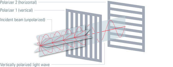
Fig. 2: Sunlight or light produced by a bulb is unpolarized. That means that the electromagnetic waves oscillate in all orientations. If unpolarized light passes a polarizer 1, light with a well-defined polarization is produced, in this case vertically polarized light. If this polarized light then hits polarizer 2, which is turned by 90°, no light will pass polarizer 2. Hence, if two polarizer are turned 90° in respect to each other they are in the so called "dark position" as no more light can be seen behind the second polarizer.
It is important that the polarization axis of the birefringent material that is inspected is in the same polarization axis as the light produced by the first polarizer. Therefore, many polarizing microscopes are equipped with a rotating stage to ensure easy alignment of the object’s polarization plane to the polarization plane of the first polarizing filter. Various accessories are available for special applications in polarization microscopy.
A Bertrand lens is used for conoscopic observation of patterns of crystals focused in the objective rear aperture. Additionally, a retardation plate or compensator is useful for quantitative analysis of birefringent specimens.

Fig. 3: Inclusion of a fly in Baltic amber. Although amber is an amorphous substance and in theory optically isotropic, the flow structures of the resin due to internal strain as well as the strain caused by the inclusions can be visualised in polarised light. The use of polarized light and the first-order red compensator lead to intensive colours in the otherwise golden amber. Combination of darkfield and incident light (glass-fibre), crossed polarizers, red-1 compensator, HDRI tone mapping. Courtesy of Michael Hügi, Swiss Gemmological Society, Bern, Switzerland.
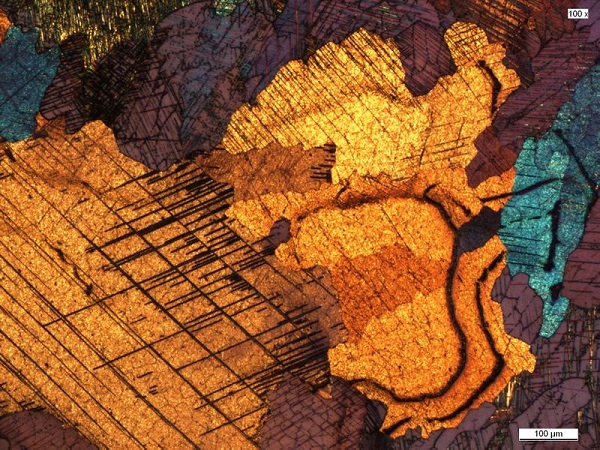
Fig. 4: Cobalt, cold-rolled, Beraha etch, polarization. The examination of microstructure morphology plays a decisive role in materials science and failure analysis. Color contrast and specific microstructure formations can frequently be enhanced by optical polarization of the etched samples under the polarizing microscope. Courtesy of Ursula Christian, University of Pforzheim, Germany.
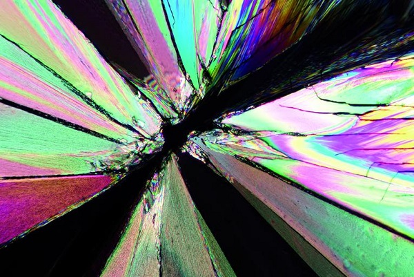
Fig. 5: Tartaric acids, polarization

Fig. 6: Aluminium, Baker etching, polarization