|
Stereo microscopes are often nicknamed the workhorse of the lab or the production department. Users spend many hours behind the ocular inspecting, observing, documenting or dissecting samples. Which factors need to be considered when selecting a stereo microscope? The answer is: "It depends". Why is that? Because it depends on the application, on the task the user wants to achieve. Basically, a stereo microscope is a tool for magnifying a three-dimensional object in three dimensions. Unlike a compound microscope, a stereo microscope is able to cope with this task. |
 |
Binocular microscopes of the old days featured a simple lens system and the same design as traditional compound microscopes. These dissecting
microscopes, as they were then known, were used primarily in biology for dissection purposes; there were no technical applications for them at the time.
Around 1890, the American biologist and zoologist Horatio S. Greenough introduced a design principle which is still used today by all major manufacturers
of optical instruments. Stereo microscopes based on the "Greenough principle" deliver genuine stereoscopic images of a very high quality.
In 1957 the American Optical Company introduced the modern stereo microscope design with a shared main objective and named it Cycloptic®. Its modern
aluminum housing contained two parallel beam paths and the main objective, as well as a five-step magnification changer. This stereo microscope type,
which was based on the telescope or CMO (Common Main Objective) principle, was adopted in addition to the Greenough type by all manufacturers
and used for modular, high-performance instruments. Two years later, another American company, Bausch & Lomb, presented its StereoZoom®Greenough
design with a groundbreaking innovation: a stepless magnification changer (zoom). Almost all of today’s designs are based on a zoom system.
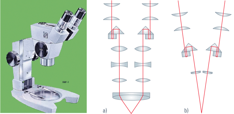
Fig. 1 (left): Cycloptic®, the first modern stereomicroscope based on the telescope principle
Fig. 2a, b (right): Two basic stereo microscope principles. a: the telescope or CMO principle b: the Greenough principle.
Stereo microscopes are still based on the mentioned technical approaches – Greenough or CMO principle – today. Which other factors need to
be considered? Four things need to be carefully assessed:
a) What is the application?
b) Which structures need to be observed, documented or visualized?
c) How many people are using the microscope?
d) What is the available budget for the solution?
Once the above factors are known it boils down to the following criteria
1. Magnification, zoom range and object field
2. Depth of field and numerical aperture
3. Optical quality and working distance
4. Ergonomics
5. Illumination
The total magnification of stereo microscopes is the combined magnification of the magnification changer, the objective and the eyepieces.
The magnification changer or zoom body
Like a magnifying glass, the magnification changer consists of optical lenses that can be used to change the magnification of the instrument. Changing the position of the magnification changer alters the degree to which the image is magnified. The degree to which the image is magnified is called the magnification factor. Modern stereo microscopes are able to provide up to 16x magnification (zoom body only) with a 20.5:1 zoom range and feature motorization or encoding to allow reliable measurements.
Next, the image is magnified further by the eyepieces. To find out the magnification of the object he or she is observing in the eyepieces, the user has to multiply the magnification factors of the magnification changer and the eyepieces.
For the sake of completeness, however, here is the formula:

MTOT VIS is the total magnification that we want to calculate. VIS stands for "visual".
z is the level of the magnification changer.
ME is the magnification of the eyepiece.
MO is the magnification of the main objective (1x in case no supplementary lens is used in a Greenough System
When looking into the eyepieces from the proper distance and with the interpupillary distance set correctly, a circular area called the object field is visible. The diameter of the object field changes depending on the magnification. In other words, a mathematical relationship exists between the magnification and the diameter of the object field. Eyepieces with 10x magnification provide a field number of 23. That means at a 1x magnification of the zoom body and the main objective the object field is 23 mm in size. At 3x magnification the object field is reduced to one third, i.e. the object field has a diameter of only 7.66 mm.
In microscopy, depth of field is often seen as an empirical parameter. In practice it is determined by the correlation between numerical aperture, resolution and magnification. For the best possible visual impression, the adjustment facilities of modern microscopes produce an optimum balance between depth of field and resolution – two parameters which in theory are inversely correlated.
Practical values for visual depth of field
The author of the first publication on the subject of visibly experienced depth of field was Max Berek, who published the results of his extensive experiments as early as 1927. Berek’s formula gives practical values for visual depth of field and is therefore still used today.
In its simplified form, it is as follows:

TVIS: visually experienced depth of field
n: Refractive index of the medium in which the object is situated. If the object is moved, the refractive index of the medium that forms the changing working distance is entered in the equation.
λ: Wavelength of the light used, for white light, λ = 0.55 μm
NA: Numerical aperture on the side of the object
MTOT VIS: Total visual magnification of the microscope
If in the above equation the total visual magnification is replaced by the relationship of useful magnification (MTOT VIS = 500 to 1,000 x NA), it can be seen that, to a first approximation, the depth of field is inversely proportional to the square of the numerical aperture.
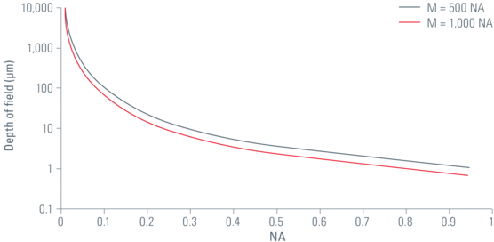
Fig. 3: Depth of field as a function of the NA for λ = 0.55 mm and n = 1.
Particularly at low magnifications, the depth of field can be significantly increased by stopping down, i.e. reducing the numerical aperture. This is normally done with the aperture diaphragm or a diaphragm on a conjugated plane. However, the smaller the numerical aperture, the lower the lateral resolution.
It is therefore a matter of finding the optimum balance of resolution and depth of field depending on the structure of the object. In the case of stereo microscopes it is often necessary to make a certain compromise in favor of higher depth of field, as the z-dimension of three-dimensional structures frequently demands it.
|
Even more depth of field – FusionOpticsTM
A sophisticated optical approach that cancels the correlation between resolution and depth of field in stereo microscopes is FusionOptics™. Here, one of the light paths provides one eye of the observer with an image of high resolution and low depth of field. Via the second light path, the other eye sees an image of the same object with low resolution and high depth of field.
The human brain combines the two separate images into one optimal overall image that features both high resolution and high depth of field. Another example illustrating the phenomenal capabilities of the human brain is the Greenough stereo microscope. Here, the object planes of the left and right light paths are at a slight angle to each other. In the overall image, the entire hatched area appears to be sharply focused, although this is not the case in either the left or the right image. |
 |
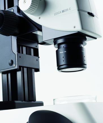
Fig. 5: Modern stereo microscope featuring a 20.5:1 zoom range with APO corrected optics and FusionOptics™.
The optical quality for stereo microscopes is usually listed as Achro or Achromat (achromatic), and as Apo (apochromatic) for the highest degree of correction for spherical and chromatic aberrations. Field curvature corrections are abbreviated Plan, while PlanApo designates a combination of chromatic aberration and field curvature correction.
|
Achro, Achromat |
Achromatic aberration correction |
|
Plan |
Flat field optical correction |
|
PlanApo |
Apochromatic and flat field correction |
In optical instruments such as stereo microscopes, achromatic aberration is a type of distortion in which there is a failure of a lens to focus all colors to the same convergence point. It occurs because lenses have a different refractive index for different wavelengths of light (the dispersion of the lens). The refractive index decreases with increasing wavelength. The aim of a good optical design is to reduce or eliminate this effect completely.
An achromatic lens or achromat is a lens that is designed to limit the effects of chromatic and spherical aberration. Achromatic lenses are corrected to bring two wavelengths (typically red and blue) into focus in the same plane. These types of lenses or microscopes are used for tasks where color reproduction is not imperative and mainly geometrical characteristics are assessed. Apochromatic lenses on the other hand are designed to correct three wavelengths (red, green, and blue) and bring them into focus in the same plane.
Working distance
This is the distance between the objective front lens and the top of the specimen when the specimen is in focus. In most instances, the working distance of an objective decreases as magnification increases. In stereo microscopy, working distance is one of the most important criteria, since it has a direct impact on the usability of the microscope as a tool.
|
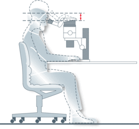
Ergonomics – people are very different
There are tall and short people and this makes instrument requirements a personal matter. For example, the existing height of a microscope equipped for a certain task with accessories and with a particular working distance may be quite unsuitable for the specific user. If the viewing height is too low, the observer will be forced to bend forward while working, resulting in muscular tension in the neck region. Ideally, therefore, the viewing height and the viewing angle of the microscope should be adjustable to the build of the user. In addition, a variable viewing height is the best way to prevent an entirely sedentary posture. It permits the observer to adopt a personal sitting posture and to change it periodically in accordance with the natural urge to shift around from time to time. It is true that the height of the chair can be altered so that a relaxed, slightly bent posture is substituted for the previous rigidly upright one, but this is not the best approach. It is much simpler and more comfortable to use a variable binocular tube in order to compensate for the height difference.
Thanks to the modular product approach, stereo microscopes with a CMO design offer many ways of tailoring the instrument to the user’s size or working habits and are therefore the preferred solution. |
 |
In stereo microscopy, illumination is the key that will bring all of the work to light. The correct illumination will allow the required structures to be visualized or perhaps new information about a sample to be discovered, just by changing the type of light. It is important that the illumination is matched correctly to the right microscope and the right application.

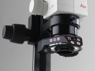
Fig. 7: Modern stereo microscope illumination systems are based on long-lasting LEDs and provide unique ways to integrate the solution into the overall microscope system. Highly integrated ring light with applied polarizer to reduce glare on the specimen.
Careful assessment of the application requirement for the stereo microscope is the key element for lasting satisfaction of the user. Since it is the workhorse of the laboratory or the production department, decision makers need to ensure that they are able to tailor the instrument 100% to user requirements. This requires a microscopy solution provider who is able to cope with this demanding requirement.