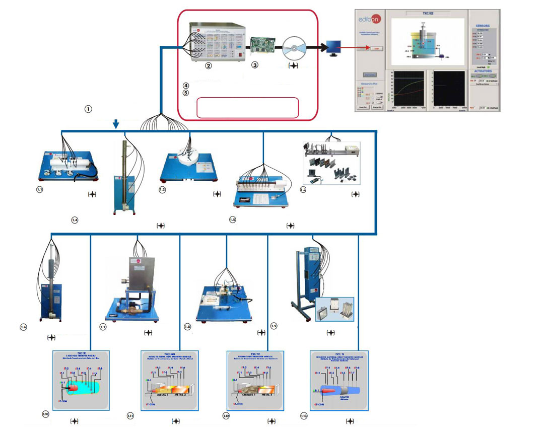
 SCADA EDIBON Computer Control System TXC/CC. Combined Free and Forced Convection and Radiation Module Control
Practices to be done with the (TXC/CL): Linear Heat Conduction Module
1.- Conduction through a simple bar.
2.- Conduction through a compound bar.
3.- Determination of the thermal conductivity “k” of different materials (conductors and insulators).
4.- The thermal conductivity properties of insulators may be found by inserting paper or other elements between the heating and cooling sections.
5.- Insulation effect.
6.- Determination of the thermal contact resistance R . tc
7.- Effect of the crossing sectional area.
8.- Understanding the use of the Fourier equation in determining rate of heat flow through solid materials.
9.- Observing unsteady-state conduction.
10.-Calibration of the temperature sensors.
11-29.- Practices with PLC
Practices to be done with the : Radial Heat Conduction Module (TXC/CR)
30.- Radial conduction.
31.- Determination of the thermal conductivity “k”.
32.- Determination of the thermal contact resistance R . tc
33.- Effect of the crossing sectional area.
34.- Insulation effect.
35.- Understanding the use of the Fourier equation in determining rate of heat flow through solid materials.
36.- Calibration of the temperature sensors.
37-55.- Practices with PLC.
Practices to be done with the Radiation He Conduction Module (TXC/RC):
56.- Inverse of the distant square law for the radiation.
57.- Stefan Boltzmann Law.
58.- Emission power I.
59.- Emission power II.
60.- Kirchorff Law.
61.- Area factors.
62.- Inverse of the distant square law for the light.
63.- Lambert´s Cosine Law.
64.- Lambert Law of Absorption.
65.- Sensors calibration.
66-84.- Practices with PLC.
Practices to be done with the Combined Free and Forced Convection and Radiation Module(TXC/CC): Practices to be done with the Extended Surface Heat Transfer Module(TXC/SE):
85.- Demonstration of the combined transmission effect of the radiation and convection on the surface of the cylinder. Determination of the combined transmission effect of heating by forced convection and radiation.
86.- Demonstration of the influence of air flow in the heating transfer. Determination of the combined transmission effect of heating by forced convection and radiation.
87.- Demonstration of the influence of input power in the heating transfer. Determination of the combined transmission effect of heating by forced convection and radiation.
88.- Demonstration of the combined transmission effect of the radiation and convection on the surface of the cylinder. Determination of the combined transmission effect of heating by free convection and radiation.
89.- Determination of the airflow.
90.- Control System: Temperature sensors calibration.
91.- Control System: Air flow sensor calibration.
92-110.- Practices with PLC.
111.-Heat transfer from a Fin.
112.- Effect of cross section shape in heat transfer from a Fin.
113.- Heat transfer from Fins of two different materials.
114.- Measuring the temperature distribution along an extended surface.
115.- Sensor calibration.
116-134.- Practices with PLC.
Practices to be done with the Radiation Errors in Temperature Measurement Module (TXC/ER):
135.- Radiation errors in temperature measurement.
136.- Measurement the errors in thermocouples in function of its painting, material of its capsules, size.
137.- Effect of air velocity on measurement error.
138.- Control System: Temperature sensors calibration.
139.- Control System: Air flow sensors calibration.
140-158.- Practices with PLC.
Practices to be done with the Unsteady State Heat Transfer Module ¥ (TXC/EI):
159.-Predicting temperature at the center of a cylinder using transient conduction with convection.
160.-Predicting the conductivity of a similar shape constructed from a different material.
161.-Conductivity and temperature dependence on volume.
162.-Conductivity and temperature dependence on surrounding temperature T .
163.- Sensors calibration.
164-182.- Practices with PLC.
Practices to be done with the Thermal Conductivity of Liquids and Gases Module (TXC/LG):
183.-Obtaining of the curve of thermal conductivity of the air.
184.- Thermal conductivity in vacuum.
185.- Water thermal conductivity determination.
186.- Thermal conductivity determination of a mineral oil.
187.- Calibration of the Unit.
188.- Control System: Calibration of the sensors. Practices to be done with the Free and Forced Convection Heat Transfer Module (TXC/FF):
189.- Dry air thermal conductivity under atmospheric pressure.
190-208.- Practices with PLC.
209.-Demonstration of the basic principles of free and forced convection.
210.- Comparison between free and forced convection.
211.- Free convection in flat surfaces.
212.- Forced convection in flat surfaces.
213.- Dependence of the heat transmission with the temperature.
214.- Dependence of the heat transmission with the speed of the fluid.
215.- Dependence of the heat transmission with the exchanger geometry.
216.- Temperature distribution in the additional surfaces.
217.- Study of the advantage of using spiked and bladed surfaces in heat transmission in free convection.
218.- Study of the advantage of using spiked and bladed surfaces in heat transmission in forced convection.
219.- Comparative study between the free convection of a horizontal surface and vertical surface.
220.- Sensors calibration.
221-239.- Practices with PLC.
Practices to be done with the 3 Axis Heat Transfer Module(TXC/TE):
240.-Calibration processes.
241.-Temperature sensors calibration.
242.-Determination of the thermal conductivity “k”, through 3 axis.
243-261.- Practices with PLC. Practices to be done with the Metal to Metal Heat Transfer Module (TXC/MM):
262.-Calibration processes.
263.-Temperature sensors calibration.
264.-Determination of the thermal conductivity “k”.
265.-Insulation effect.
266.-Determination of the thermal contact resistance.
267-285.- Practices with PLC. Practices to be done with the Ceramic Heat Transfer Module (TXC/TC):
286.-Calibration processes.
287.-Temperature sensors calibration.
288.-Determination of the thermal conductivity “k”.
289.-Calculation of the heat transfer properties of specimens.
290-308.- Practices with PLC. Practices to be done with the Isolated Material Heat Transfer Module(TXC/TI):
309.-Calibration processes.
310.-Temperature sensors calibration.
311.-Determination of the thermal conductivity “k”.
312.-Calculation of the heat transfer properties of specimens.
313-331.- Practices with PLC.
1.1 TXC/CL. Linear Heat Conduction Module:
Unit to study the principles of linear heat conduction and to allow the conductivity of various solid conductors and insulators to be measured. It is given with interchangeable samples of different materials, different diameters and different insulating materials that allow to demonstrate the area effects, the conductivity and the combinations in series in the heat transmission process.
Anodized aluminium structure and panel in painted steel. Diagram in the front panel with similar distribution to the elements in the real unit.
Input heat section. Electric heater (heating resistance) with power regulation (150W), computer controlled. Refrigeration section with a surface cooled by water. Central sections: with brass of 25 mm of diameter, with brass of 10 mm of diameter and with stainless steel of 25 mm of diameter.
Water flow regulation valve.
Sensors: 11 temperature sensors distributed in the heating section, refrigeration section and central sections; 1 temperature sensor at the water inlet of the unit; 1 temperature sensor at the water outlet of the unit and a water flow sensor.
Power measurement from the computer (PC).
Cables and Accessories, for normal operation.
This unit is supplied with 8 manuals.
Computer Control+Data Acquisition+Data Management Software for this Module:
Flexible, open and multicontrol software. Management, processing, comparison and storage of data.
Sampling velocity up to 250,000 data per second. It allows the registration of the alarms state and the graphic representation in real time.
Dimensions (approx.): 400 x 300 x 300 mm. Weight: 20 Kg.
This module requires Control Interface Box (TSTCC/CIB) and Data Acquisition Board (DAB).
1.2 TXC/CR. Radial Heat Conduction Module:
Unit to study the principles of radial heat conduction, and to allow the conductivity of solid brass disk to be
measured. Anodized aluminium structure and panel in painted steel. Diagram in the front panel with similar distribution to the elements in the real unit.
Brass disk of 110 mm of diameter and 3 mm of thickness. Incorporated electric heater (150W), computer controlled. Peripherical cooling tube. Water flow sensor. Water flow regulation valve.
8 Temperature sensors: 6 temperature sensors distributed in the unit 1 temperature sensor at the water inlet of the unit and 1 temperature sensor at the water outlet of the unit.
Power measurement from the computer (PC).
Cables and Accessories, for normal operation.
This unit is supplied with 8 manuals.
Computer Control+Data Acquisition+Data Management Software for this Module:
Flexible, open and multicontrol software. Management, processing, comparison and storage of data.
Sampling velocity up to 250,000 data per second. It allows the registration of the alarms state and the graphic representation in real time.
Dimensions (approx.): 400 x 300 x 300 mm. Weight: 20 Kg.
This module requires Control Interface Box (TSTCC/CIB) and Data Acquisition Board (DAB).
1.3 TXC/RC. Radiation Heat Conduction Module:
Unit designed to demonstrate the laws of radiant heat transfer and radiant heat exchange.
It basically consists in two independent parts. One of the parts is for the light radiation experiments and another part is for the thermal radiation experiments. The elements provided with the unit allow making the measuring of the temperature, radiation, intensity light and the power in the resistance or bulb. Anodized aluminium structure and panels in painted steel. Diagram in the front panel with similar distribution to the elements in the real unit.
This unit consists on a metal plate with a resistance at one side and a lamp in the another side. Lengthwise of the metal plate you can place the elements supplied with the unit.
Heating resistance, computer controlled.
Lamp, with diffuser.
The unit is provided with accessories for light experiments and radiation experiments.
Light accessories: Luxmeter that allows to measure the intensity of the light. Filters: 3 Grey Neutral Density A153 filters, 1 Grey Neutral Density A152 filter and 1Grey Neutral Density A154 filter. Filter portholes.
Radiation accessories: Radiometer (it allows to measure the intensity of the radiation). Planes surfaces ( they are elements for studying the radiation and each one contains one temperature sensor). Variable slit or aperture (it allows to regulate the area of the radiation).
7 Temperature sensors.
Power measurement from the computer (PC).
Radiation measurement from the computer (PC).
Cables and Accessories, for normal operation.
This unit is supplied with 8 manuals.
Computer Control+Data Acquisition+Data Management Software for this Module:
Flexible, open and multicontrol software. Management, processing, comparison and storage of data.
Sampling velocity up to 250,000 data per second. It allows the registration of the alarms state and the graphic representation in real time.
Dimensions (approx.): 1400 x 500 x 500 mm. Weight: 40 Kg.
This module requires Control Interface Box (TSTCC/CIB) and Data Acquisition Board (DAB).
1.4 TXC/CC. Combined Free and Forced Convection and Radiation Module:
Unit to study the principles of combined free and forced convection with radiation from a horizontal heater cylinder. It studies the variation experimented by the local heat transfer coefficient around of a horizontal cylinder. It is subject to a forced and a free convection.
Diagram in the front panel with similar distribution to the elements in the real unit.
Centrifugal fan (computer controlled) of 2650 rpm, which provides a maximum flow of 1200l/min.
Stainless steel conduct with interior cover, including: temperature sensor in order to measure the temperature of inlet air, flow sensor and temperature sensor in order to measure the temperature of outlet air.
Heater: copper cylinder with exterior cover: interior resistance of 150W., temperature sensor for measuring the temperature of the cylinder.
Power measurement from the computer (PC).
Cables and Accessories, for normal operation.
This unit is supplied with 8 manuals.
Computer Control+Data Acquisition+Data Management Software for this Module:
Flexible, open and multicontrol software. Management, processing, comparison and storage of data.
Sampling velocity up to 250,000 data per second. It allows the registration of the alarms state and the graphic representation in real time.
Dimensions (approx.): 430 x 350 x 1300 mm. Weight: 50 Kg.
This module requires Control Interface Box (TSTCC/CIB) and Data Acquisition Board (DAB).
1.5 TXC/SE. Extended Surface Heat Transfer Module:
Unit designed to demonstrate the temperature profiles and heat transfer characteristics for an extended surface. It studies the effect of adding fins to a body in order to extend its surface for a change in the cooling rate. Fins of different materials and cross section shapes are used to analyse the effect of cooling.
Diagram in the front panel with similar distribution to the elements in the real unit.
150 W Resistance, embedded in a copper capsule, to permit a good contact with the interchangeable fins.
The fins are interchangeable, providing two different materials: brass and stainless steel and three different cross section shapes: square, circular and hexagonal.
The power to the resistance is controlled from the computer with the SCADA software.
11 Temperature sensors.
Power measurement from the computer (PC).
Cables and Accessories, for normal operation.
This unit is supplied with 8 manuals.
Computer Control+Data Acquisition+Data Management Software for this Module:
Flexible, open and multicontrol software. Management, processing, comparison and storage of data.
Sampling velocity up to 250,000 data per second. It allows the registration of the alarms state and the graphic representation in real time.
Dimensions (approx.): 600 x 300 x 175 mm. Weight: 20 Kg.
This module requires Control Interface Box (TSTCC/CIB) and Data Acquisition Board (DAB).
1.6 TXC/ER. Radiation Errors in Temperature Measurement Module:
Unit to demonstrate how temperature measurements can be influenced by sources of thermal radiation.
The objective of this module is to measure the error in a black thermocouple due the radiation with respect with another normal thermocouple where there are not radiative shielding in comparison when there are radiative shielding, error in function of material of the thermocouple’s capsule, size of the thermocouple, etc.
Diagram in the front panel with similar distribution to the elements in the real unit.
Centrifugal fan (computer controlled): 2650 rpm. Maximum flow of 1200l/min.
Stainless steel conduct with interior cover, including: temperature sensor, in order to measure the temperature of inlet air; flow sensor and temperature sensor, in order to measure the temperature of outlet air.
Copper cylinder with exterior cover: interior resistance of 150W; temperature sensor for measuring the temperature of the cylinder.
5 Temperature sensors with different styles and sizes of bead installed in the duct to demonstrate the differences in readings obtained.
Power measurement from the computer (PC).
Cables and Accessories, for normal operation.
This unit is supplied with 8 manuals.
Computer Control+Data Acquisition+Data Management Software for this Module:
Flexible, open and multicontrol software. Management, processing, comparison and storage of data.
Sampling velocity up to 250,000 data per second. It allows the registration of the alarms state and the graphic representation in real time.
Dimensions (approx.): 430 x 350 x 1300 mm. Weight: 50 Kg.
This module requires Control Interface Box (TSTCC/CIB) and Data Acquisition Board (DAB).
1.7 TXC/EI. Unsteady State Heat Transfer Module:
Unit designed to allow practices and exercises to be performed in unsteady state heat transfer. It studies the transient conduction with convection. Using different shapes (rectangular slabs, spheres and cylinders) of different materials, the temperature of other shapes and materials can be predicted.
Diagram in the front panel with similar distribution to the elements in the real unit.
Dual concentric open top tanks filled with water, total tank capacity: 40 litres, 300 x 350 x 400 mm.
concentric tank: 1.2 l., diameter: 70 mm.
Different shapes of different size and material are studied: brass spheres, stainless steel spheres, brass cylinder, stainless steel cylinder, aluminium rectangular slab and stainless steel rectangular slab.
Each shape is fitted with a temperature sensor at the center of the object.
The shapes are installed in special holder at the center of the top cover of the large tank. The holder also has a temperature sensor that enters in the water bath at the same time as the shape.
Heating element, computer controlled, with a power of 3000 W.
Water pump with variable speed.
Sensors: 3 Temperature sensors allow controlling the stability of the temperature of the water bath. Flow sensor. 2 Temperature sensors: the first one permits to record the evolution of the temperature of the shape at its center and the second one, works as a stopwatch, it will indicate the precise moment in which the shape is submerged.
Level switch. Power measurement from the computer (PC).
Cables and Accessories, for normal operation.
This unit is supplied with 8 manuals.
Computer Control+Data Acquisition+Data Management Software for this Module:
Flexible, open and multicontrol software. Management, processing, comparison and storage of data.
Sampling velocity up to 250,000 data per second. It allows the registration of the alarms state and the graphic representation in real time.
Dimensions (approx.): 600 x 600 x 750 mm. Weight: 60 Kg.
This module requires Control Interface Box (TSTCC/CIB) and Data Acquisition Board (DAB).
1.8 TXC/LG. Thermal Conductivity of Liquids and Gases Module:
This unit has been designed to enable students to easily determine the thermal conductivity of liquids and gases. By the realization of the practices the student can determine the thermal conductivity of any suitable gas or compatible liquid with materials on construction.
Diagram in the front panel with similar distribution to the elements in the real unit.
Aluminium body (cylinder) with brass jacket that contains the test fluid and the refrigeration water.
Variable heating resistance (in the cylinder), computer controlled, (150 W).
6 Temperature sensors. Valves. Syringe.
Power measurement from the computer (PC).
Cables and Accessories, for normal operation.
This unit is supplied with 8 manuals.
Computer Control+Data Acquisition+Data Management Software for this Module:
Flexible, open and multicontrol software. Management, processing, comparison and storage of data.
Sampling velocity up to 250,000 data per second. It allows the registration of the alarms state and the graphic representation in real time.
Dimensions (approx.): 500 x 400 x 300 mm. Weight: 40 Kg.
This module requires Control Interface Box (TSTCC/CIB) and Data Acquisition Board (DAB).
1.9 TXC/FF. Free and Forced Convection Heat Transfer Module:
This unit allows to study the efficiency of different exchangers, analyzing the heat transmission coefficients of each of the exchangers exposed to different airflows. A fan placed in the upper part of the tunnel allows controlling the airflow that goes through the tunnel.
Diagram in the front panel with similar distribution to the elements in the real unit.
Stainless steel tunnel of rectangular section, 700 mm long. In the tunnel three type of different heat exchangers can be set.
Methacrylate viewer that allows a good visualization of the exchanger that is in use.
Stabilizers to guarantee an uniform air flux.
9 Temperature sensors: 2 Temperature sensors measure the air temperature at the inlet and outlet of the area of heat exchange. Temperature measurements, at different distances of the base of the dowels and blade exchangers, are made by other five temperature sensors that are introduced by one side of the tunnel. 1 temperature sensor for the heating resistance. 1 temperature sensor in the exchangers.
Flow sensor, for measuring the air flow generated.
3 Aluminium exchangers: flat heat exchanger, dowels heat exchanger, blade heat exchanger.
Heating resistance of 150W for each exchanger, computer controlled.
Variable speed fan, computer controlled.
Cables and Accessories, for normal operation.
This unit is supplied with 8 manuals.
Computer Control+Data Acquisition+Data Management Software for this Module:
Flexible, open and multicontrol software. Management, processing, comparison and storage of data.
Sampling velocity up to 250,000 data per second. It allows the registration of the alarms state and the graphic representation in real time.
Dimensions: 370 x 610 x 920 mm. Weight: 25 Kg.
This module requires Control Interface Box (TSTCC/CIB) and Data Acquisition Board (DAB).
1.10 TXC/TE. 3 Axis Heat Transfer Module:
Diagram in the front panel with similar distribution to the elements in the real unit.
3 Axis conduction module.
Electric heater (heating resistance), computer controlled.
8 Temperature sensors.
Cables and Accessories, for normal operation.
This unit is supplied with 8 manuals.
Computer Control+Data Acquisition+Data Management Software for this Module:
Flexible, open and multicontrol software. Management, processing, comparison and storage of data.
Sampling velocity up to 250,000 data per second. It allows the registration of the alarms state and the graphic representation in real time.
Dimensions: 300 x 300 x 300 mm. Weight: 20 Kg.
This module requires Control Interface Box (TSTCC/CIB) and Data Acquisition Board (DAB).
1.11 TXC/MM. Metal to Metal Heat Transfer Module:
Diagram in the front panel with similar distribution to the elements in the real unit.
Electric heater (heating resistance), computer controlled.
6 Temperature sensors.
Materials to test: copper, brass, stainless steel, aluminium (to choose).
Cables and Accessories, for normal operation.
This unit is supplied with 8 manuals.
Computer Control+Data Acquisition+Data Management Software for this Module:
Flexible, open and multicontrol software. Management, processing, comparison and storage of data.
Sampling velocity up to 250,000 data per second. It allows the registration of the alarms state and the graphic representation in real time.
Dimensions: 300 x 300 x 300 mm. Weight: 20 Kg.
This module requires Control Interface Box (TSTCC/CIB) and Data Acquisition Board (DAB).
1.12 TXC/TC. Ceramic Heat Transfer Module:
Diagram in the front panel with similar distribution to the elements in the real unit.
Electric heater (heating resistance), computer controlled.
6 Temperature sensors.
Suitable for ceramic materials.
Cables and Accessories, for normal operation.
This unit is supplied with 8 manuals.
Computer Control+Data Acquisition+Data Management Software for this Module:
Flexible, open and multicontrol software. Management, processing, comparison and storage of data.
Sampling velocity up to 250,000 data per second. It allows the registration of the alarms state and the graphic representation in real time.
Dimensions (approx.): 300 x 300 x 300 mm. Weight: 25 Kg.
This module requires Control Interface Box (TSTCC/CIB) and Data Acquisition Board (DAB).
1.13 TXC/TI. Isolated Material Heat Transfer Module:
Diagram in the front panel with similar distribution to the elements in the real unit.
Electric heater (heating resistance), computer controlled.
8 Temperature sensors.
Suitable for fibrous, granular and sheet materials.
Suitable for homogeneous and non-homogeneous materials.
Suitable for soft, semi-rigid and rigid materials.
Cables and Accessories, for normal operation.
This unit is supplied with 8 manuals.
Computer Control+Data Acquisition+Data Management Software for this Module:
Flexible, open and multicontrol software. Management, processing, comparison and storage of data.
Sampling velocity up to 250,000 data per second. It allows the registration of the alarms state and the graphic representation in real time.
Dimensions (approx.): 300 x 300 x 300 mm. Weight: 20 Kg.
This module requires Control Interface Box (TSTCC/CIB) and Data Acquisition Board (DAB).
Items Common for the Modules type “TXC”
2. TSTCC/CIB. Control Interface Box:
This control interface is common for the modules type “TXC” and can work with one or several modules.
Control interface box with process diagram in the front panel.
The unit control elements are permanently computer controlled.
Simultaneous visualization in the computer of all parameters involved in the process.
Calibration of all sensors involved in the process.
Real time curves representation about system responses.
All the actuators’ values can be changed at any time from the keyboard.
Shield and filtered signals to avoid external interferences.
Real time PID control with flexibility of modifications from the computer keyboard of the PID parameters, at any moment during the process. Real time PID control for parameters involved in the process simultaneously. Open control allowing modifications, at any time and in a real time, of parameters involved in the process simultaneously.
Three safety levels, one mechanical in the unit, other electronic in the control interface and the third one in the control software.
Dimensions (approx.): 490 x 330 x 310 mm. Weight: 10 Kg.
3. DAB. Data Acquisition Board:
PCI Data acquisition National Instruments board to be placed in a computer slot.
16 Analog inputs. Sampling rate up to: 250 KS/s. 2 Analog outputs. 24 Digital Inputs/Outputs.
Hiện tại chưa có ý kiến đánh giá nào về sản phẩm. Hãy là người đầu tiên chia sẻ cảm nhận của bạn.