Notice: Undefined index: en in /var/www/html/redstarvietnam.com/public_html/core/functions/function_global.php on line 0

Warning: Invalid argument supplied for foreach() in /var/www/html/redstarvietnam.com/public_html/core/functions/function_global.php on line 0
SERIN/CCB - Bộ thí nghiệm giảng dạy hệ thống mô-tơ Servo DC cơ bản
Red Star Vietnam Co., Ltd.
Icons giỏ hàng Cart 0
Total : đ

SERIN/CCB - Bộ thí nghiệm giảng dạy hệ thống mô-tơ Servo DC cơ bản

State: Out of stock
“SERIN/CCB” là thiết bị với mục đích chính để nghiên cứu hệ thống công suất thấp. Cho phép mô phỏng tốc độ động cơ công suất thấp.
Bộ thí nghiệm cơ bản điều khiển máy tính để nghiên cứu các hệ thống điều khiển vòng lặp và vòng đóng. Bao gồm một hệ thống điện cơ với động cơ DC và một máy đo tốc độ gắn trên hộp bao gồm các tầng công suất và bộ thu dữ liệu và bảng điều khiển và các phần mềm điều khiển.
Bộ thiết bị này cho phép điều khiển đóng, mở, lặp và khởi động các biến, tỷ lệ khuếch đại, PID, giới hạn dòng điện, mô đun PƯM, điều khiển đảo ngược, bắt đầu và dừng điều khiển. Cho phép học viên có thể chuẩn đoán tự nhiên, vị trí lỗi, mà không làm hỏng thiết bị.
Warranty: No warranty infomation


Price: Contact us


Order
  • Delivery time: 8h00 - 18h00 daily
  • Genuine product, provided width CO, CQ
  • 03 months of free warranty for consumable and accessories
  • 12 months of free warranty for main equipment
  • Accessorie's price is applied only when purchased with
    main equipment
  • Contact us for any particular accessory's quotion
Email: info@redstarvietnam.com Every day in week

Unit: SERIN/CCB. Servosystems Trainer (DC motors) Always included
in the supply:
EDIBON Computer Control System Connection to
computer (PC),
through USB port
Software for:
- Data Acquisition
- Data Management
- Computer Control
Cables and Accessories Manuals Computer
(not included
in the supply)


Process diagram and unit elements allocation:


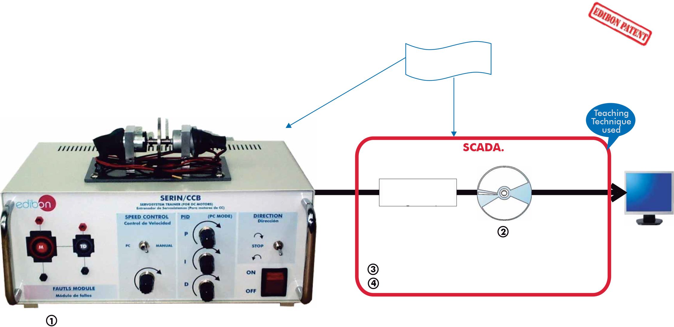
Unit control may be done manually, on the unit itself, basically or in a more advance way through the control software SCADA. This control software can do two kinds of control:

Open-loop and Closed-loop control.
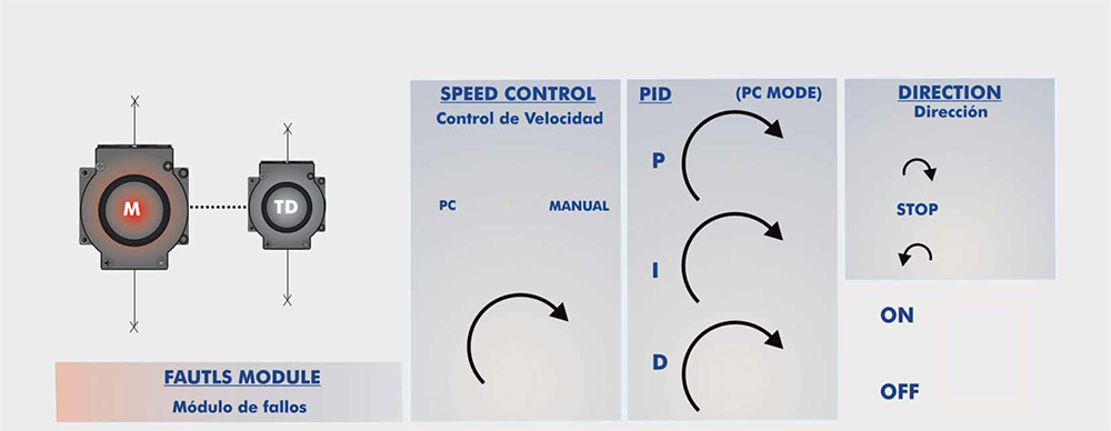
The base unit has four different parts as seen on the front panel:
- Connection zone for motor and tachogenerator.
- Manual or Compute rised Speed control. There is a lever-like switch for selecting the kind of control.
- PID zone. Here, the values of the PID constants can be manipulated (Proportional, Integral and Derivative).

This functionality is only available for PC mode, the speed control lever has to point to PC.
- Turning and stop control zone. Allows changing the turning sense and stopping the motor.
Simple integrated circuits to be able to analyse independently each functional stage.
Visible components with 2 mm connectors for voltage and current measurement.
Control through PWM pulses and power stage configured with MOSFET transistors.


Exercises and practical possibilities:

Some Practical Possibilities of the Unit:


1.- Open loop control response.
2.- Demonstration of a bracking ramp functioning.
3.- Functioning of a PWM modulator and the response of the system.
4.- Closed loop or feedback control through a Proportional control (P).
5.- Closed loop or feedback control through a Derivative control (D).
6.- Closed loop or feedback control through a Proportional-Integral controller (PI).
7.- Closed loop or feedback control through a Proportional- Derivative controller (PD).
8.- Achievement of an over damped system using a closed loop system.
9.- Achievement of a critically damped system using a closed loop PID.
10.- Instability, a characteristic of closed loop systems.
11.- Stabilisation of an unstable system.
12.- Faults simulation:


Type of faults including on the unit:
Fault 1: The absolute value of the feedback signal from the
tachogenerator is not calculated for its subtraction
from the reference, thus, for one of the turning
senses, the error is wrong.
Fault 2: The value of the Proportional constant of the PID is
divided by ten with the user unable to detect it but its
effect.
Fault 3: The value of the Integral constant of the PID is
divided by ten with the user unable to detect it but its
effect.
Fault 4: The value of the Derivative constant of the PID is
divided by ten with the user unable to detect it but its
effect.
Fault 5: The signal from the tachogenerator is modified,
making the PID control to believe that the speed is
ten times lower to the real one.
None of these faults are exclusive, being possible to
combine them.


Steel box.
Diagram in the front panel with similar distribution to the elements in the real unit.
Electromechanic unit.
Tachometric adaptor. 
Generation and control of set point.
Ramp generator, as well as sinusoidal, triangular and square wave generator.
PWM modulator.
Open loop control.
Close loop control:
+ Proportional Control (P).
+ Integrative Proportional Control (PI).
+ Proportional derivative Control (PD).
+ Proportional Integrative derivative control (PID).
Current limiter.
Turn inversion control.
Stop/starting control.
Power stage and excitation of the power stage.
Brake control.

Fault simulator that allows the entries of a considerable amount of dysfunctions in order to the students diagnose its nature and find out the components that cause them. Without taking risks to provoke any damage in the unit.


Type of faults included in the unit:
Fault 1: The absolute value of the feedback signal from the tachogenerator is not calculated for its subtraction from the reference, thus, for one of the turning senses, the error is wrong.
Fault  2: The value of the Proportional constant of the PID is divided by ten with the user unable to detect it but its effect.
Fault  3: The value of the Integral constant of the PID is divided by ten with the user unable to detect it but its effect.
Fault  4: The value of the Derivative constant of the PID is divided by ten with the user unable to detect it but its effect.
Fault  5: The signal from the tachogenerator is modified, making the PID control to believe that the speed is ten times lower to the real one.

None of these faults are exclusive, being possible to combine them.


Direct current motor (DC) and tachometric generator.
Computer Control Software.
Cables and accessories, necessary for its correct operation.
Manuals:
This unit is supplied with several manuals:Required Services, Assembly and Installation, Starting-up, Safety, Interface and Control Software, Maintenance & Practices and simulation of faults Manuals.


Required services:

-Electrical supply: Single-phase 220-V/50Hz. of 110 V./60Hz.
-Computer (PC).


Dimensions & weight:

Dimensions 400 x 330 x 310 mm. approx.
Weights 10 Kg. approx.


  • Đánh giá sản phẩm:

(Xem mã khác)

Hiện tại chưa có ý kiến đánh giá nào về sản phẩm. Hãy là người đầu tiên chia sẻ cảm nhận của bạn.