Notice: Undefined index: en in /var/www/html/redstarvietnam.com/public_html/core/functions/function_global.php on line 0

Warning: Invalid argument supplied for foreach() in /var/www/html/redstarvietnam.com/public_html/core/functions/function_global.php on line 0
Computer Controlled Process Control Plant with Industrial Instrumentation and Service Module - CPIC
Red Star Vietnam Co., Ltd.
Icons giỏ hàng Cart 0
Total : đ

Computer Controlled Process Control Plant with Industrial Instrumentation and Service Module - CPIC

State: Out of stock
Items supplied as standard:
1. CPIC. Unit
2. CPIC/CIB.Control Interface Box
3. DAB. Data Acquisition Board
4. CPIC/CCSOF. PID Computer Control + Data Acquisition + Data Management Software
5. Cables and Accessories
6. Manuals
Warranty: No warranty infomation


Price: Contact us


Order
  • Delivery time: 8h00 - 18h00 daily
  • Genuine product, provided width CO, CQ
  • 03 months of free warranty for consumable and accessories
  • 12 months of free warranty for main equipment
  • Accessorie's price is applied only when purchased with
    main equipment
  • Contact us for any particular accessory's quotion
Email: info@redstarvietnam.com Every day in week
EDIBON SCADA System
and PID CONTROL included
Control
Interface Box
Data Acquisition
Board
Computer Control
- Software for each
- Set for Process
- Control
Cables and Accessories Manuals PID CONTROL
(Open Control + Multicontrol + Real Time Control)
- From COMPUTER (standard)
- From PLC (optional)
Unit: CPIC. Process Control Plant with Industrial Instrumentation and
Service Module (Flow, Temperature, Level and Pressure).


Practical possibilities:


1.- Familiarisation with the different components of the system and their symbolic representation.
Identification of components and description of their functions.
2.- The auxiliary systems: air and hot water supply.
3.- Flow sensors calibration.
4.- Temperature sensors calibration.
5.- Level sensor calibration.
6.- I/P converter calibration.
7.- Flow control loop (on/off).
8.- Flow control loop (proportional).
9.- Flow control loop (P+I).
10.- Flow control loop (P+D).
11.- Flow control loop (P+I+D).
12.- Adjust of the flow controller constants (Ziegler-Nichols).
13.- Adjust of the flow controller constants (reaction curves).
14.- Search of simple shortcomings in the loop of flow control.
15.- Temperature control loop (on/off).
16.- Temperature control loop (proportional).
17.- Temperature control loop (P+I).
18.- Temperature control loop (P+D).
19.- Temperature control loop (P+I+D).
20.- Adjust of the temperature controller constants (minimum area or reduction rate).
21.- Adjust of the temperature controller constants (minimum disturbance criterion).
22.- Adjust of the temperature controller constants (minimum width criterion).
23.- Study of the retards for speed/distance, exemplified through the temperature control loop.
24.- Study of the energy lost in the temperature control loop.
25.- Search of simple shortcomings in temperature control loop.
26.- Level control loop (on/off).
27.- Level control loop (proportional).
28.- Level control loop (P+I).
29.- Level control loop (P+D).

30.- Level control loop (P+I+D).
31.- Adjust of the level controller constants (minimum area or reduction rate).
32.- Adjust of the level controller constants (minimum disturbance criterion).
33.- Adjust of the level controller constants (minimum width criterion).
34.- Search of simple shortcomings in level control loop.
35.- Pressure control loop (on/off).
36.- Pressure control loop (proportional).
37.- Pressure control loop (P+I).
38.- Pressure control loop (P+D).
39.- Pressure control loop (P+I+D).
40.- Adjust of the pressure controller constants (minimum area or reduction rate).
41.- Adjust of the pressure controller constants (minimum disturbance criterion).
42.- Adjust of the pressure controller constants (minimum width criterion).
43.- Search of simple shortcomings in the pressure control loop.
44.- The use of the controllers in cascade, exemplified with the level/ flow control loop.
45.- Adjust of cascade control constants (minimum area or reduction rate).
46.- Adjust of cascade control constants (minimum disturbance criterion).
47.- Adjust of cascade control constants (minimum width criterion).
48.- Search of simple shortcomings in cascade control loop.
49.- Practical operation of the control plant to some wanted specific values: transfers without
interferences.
50.- Calculation of the fluid flow in function of the differential pressure sensor.
51-69.- Practices with PLC.

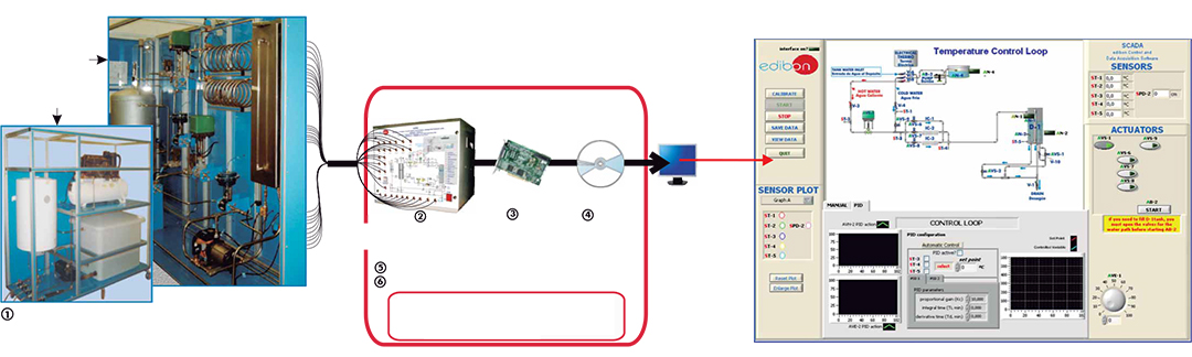
1. CPIC. Unit:

CPIC is a “Computerized Industrial Process Control Plant”, that offers, on a reasonable laboratory scale, the different process and elements that are commonly used by any kind the industry. It also shows the complexity that can take place while controlling in processes the same variable.
Metallic structure. Panels and main metallic elements in stainless steel. Diagram in the front panel with similar distribution to the elements in the real unit.

Main Unit contains the following elements:
Two pneumatics valves with C : 0.25. Actuator (I/P) from 0.2 to 1.0 bar for electric signal from 4 to 20 mA.
Two electronic valves for electric signal from 4 to 20mA.
Twelve solenoid valves, normally closed.
Two solenoid valves, normally open, placed at the air loop and flow loop.
Three differential pressure sensors.
Five temperature sensors placed along the unit to control the temperature in different lines.
One level sensor (effective length: 300 mm.).
Four level switches.
Water pump: maximum water flow: 106 l./min. and maximum pressure: 7 bar.
Stainless steel water tank: maximum capacity: 100 l.
Stainless steel tank: maximum capacity: 200 l., maximum pressure:16 bar. It has eight takings, but only six are used in this unit. In the upper part, there is a safety valve that opens when the pressure exceeds 4 bar. Two takings are used to measure the water height by the means of a differential pressure sensor. Other differential pressure sensor gives us the inner pressure.

Service Module contains the following elements:
Heater unit: A tank with a maximum capacity of 80 l. and an electrical resistance of 1.2 kW as maximum electrical power, the temperature control is placed in the
electrical resistance. It has a safety valve and purge valve. The lower part of the unit has an inlet pipe (cold water) and an outlet pipe (hot water).
Compressor unit: maximum pressure: 10 bar. This unit has a regulating valve with a
manometer to fix the outlet maximum pressure.
Water system: water tank, capacity: 400 l., water pump: 2500 l./h., the inlet pipe of the tank has an automatic filling system, drain valve in the water tank.


2. CPIC/CIB.Control Interface Box:

With process diagram in the front panel. The unit control elements are permanently computer controlled. Simultaneous visualization in the PC of all parameters involved in the process. Calibration of all sensors involved in the process. Real time curves representation. All the actuators’ values can be changed at any time from the
keyboard. Shield and filtered signals to avoid external interferences. Real time PID control with flexibility of modifications from the PC keyboard of the PID parameters, at
any moment during the process. Open control allowing modifications, at any moment and in real time, of parameters involved in the process. 3 safety levels: mechanical in the unit, electronic in the control interface and the third one in the control software.


3. DAB. Data Acquisition Board:

PCI Express Data acquisition National Instruments board to be placed in a computer slot. 16 analog inputs. Sampling rate up to: 250 KS/s. 2 Analog outputs. 24 Digital
Inputs/Outputs.


4. CPIC/CCSOF. PID Computer Control + Data Acquisition + Data Management Software:

Flexible, open and multicontrol software. Management, processing, comparison and storage of data. Sampling velocity up to 250 KS/s (kilo samples per second). It allows the registration of the alarms state and the graphic representation in real time.

 
5. Cables and Accessories, for normal operation.   

6. Manuals:

This unit is supplied with 8 manuals.
Dimensions (approx.)=
-Main Unit: Weight: 1000 Kg. 5000 x 1500 x 2500 mm.
-Service Module: 2 Weight: 200 Kg. 000 x 1500 x 2000 mm.
-Control Interface Box: 490 x 450 x 470 mm. Weight: 20 Kg.

 
  • Đánh giá sản phẩm:

(Xem mã khác)

Hiện tại chưa có ý kiến đánh giá nào về sản phẩm. Hãy là người đầu tiên chia sẻ cảm nhận của bạn.